SYSRES OAE-Probe Microphone Calibration
The calibration procedure involves two sets of measurements, and these are shown in the diagram for the physical setup. In the first measurement (a), the pressure responses of the reference microphone and probe tube are measured and the transfer function between the reference microphone and probe tube determined. In the second measurement (b), the pressure responses of the OAE probe and probe tube are measured and the transfer function between the OAE probe and the probe tube is determined. The transfer function between the OAE probe and reference microphone is determined using the transfer functions from (a) and (b). This transfer function is then multiplied by the sensitivity of the reference microphone to obtain the microphone sensitivity function of the OAE-probe microphone.
The sequence of SYSRES commands required for the calibration process is outlined here.
Physical setup of the calibration procedure. In this example, the reference microphone is the B&K ¼-inch 4944-A (Brüel & Kjær), the probe tube is the ER-7C (Etymotic Research), the OAE probe is the ER-10C (Etymotic Research) and the sound source is the ER-2A (Etymotic Research).
Determination of transfer function between the reference microphone and probe tube
Step SYSRES commands 1. Frequency response of probe tube fc
wd=Ppt12. Frequency response of reference microphone fc
wd=Pref3. Transfer function between reference microphone and probe tube no=Ppt1
wd=Hrefpt
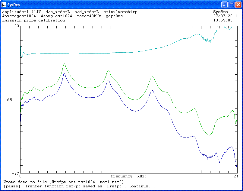
Command fc plays a chirp stimulus and command wd=Ppt1 saves the acquired response to file Ppt1.mat. Command no=Ppt1 divides the response in the SYSRES buffer (in this case the frequency response of reference microphone) by the previously saved response Ppt1.

Frequency responses of probe tube (blue) and reference microphone (green), and transfer function (cyan).
Determination of transfer function between the OAE probe and probe tube
Step SYSRES commands 4. Frequency response of OAE probe fc
wd=Pem5. Frequency response of probe tube fc
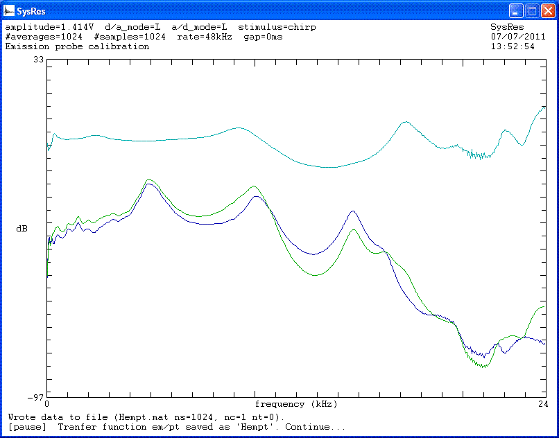
wd=Ppt26. Transfer function between the OAE probe and probe tube rd=Pem
no=Ppt2
wd=Hempt

Frequency responses of probe tube (blue) and OAE probe (green), and transfer function (cyan).
Determination of transfer function between the OAE probe and reference microphone, and computation of microphone sensitivity function of the OAE-probe
Step SYSRES commands 7. Transfer function between the OAE probe and reference microphone no=Hrefpt
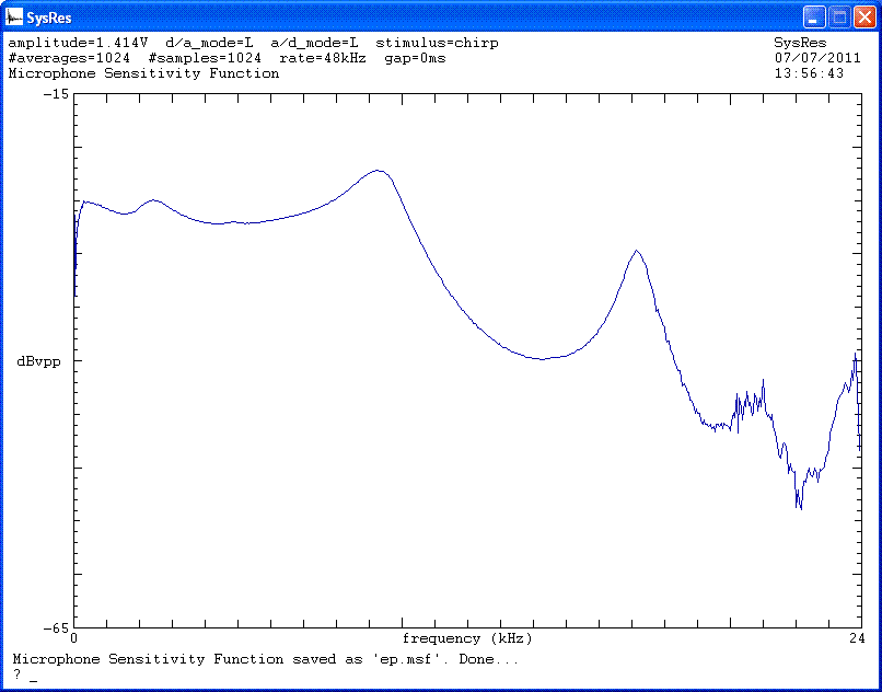
wd=Hemref8. Microphone sensitivity function of the OAE-probe sm=0.1
wd=ep.msf
The command sm=0.1 sets the microphone sensitivity to 0.1 V/Pa.

Microphone sensitivity function.
Recommended LST files
The calibration process can be completed more efficiently through the use of a list (LST) file that contains all the necessary set of SYSRES commands. The following LST files are recommended.
micCal1.lst
Intended for 1 channel sound cards. It measures the response of each microphone one at a time using 1 channel. Responses of each microphone and transfer functions are saved.
micCal2.lst
Intended for 2 channel sound cards. It measures the responses of the two microphones at the same time. Only transfer functions are saved.
micCal3.lst
Intended for 2 channel sound cards. It measures the responses of the two microphones one at a time with the probe tube always connected to the right channel. Responses of each microphone and transfer functions are saved. The screenshots above were created using micCal3.lst.
